Explain the Procedure to Test Reverse Power Relay
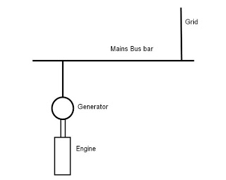
Testing a power brake booster is a fairly. If you look like this picture you can easily understand working procedure of reverse power relay normally when power passes from generator to load the breaker not trip but when generator works opposite as motor to power consumer as soon as reverse power relay active and its energized an.

Reverse Power Relay Basics And Operation
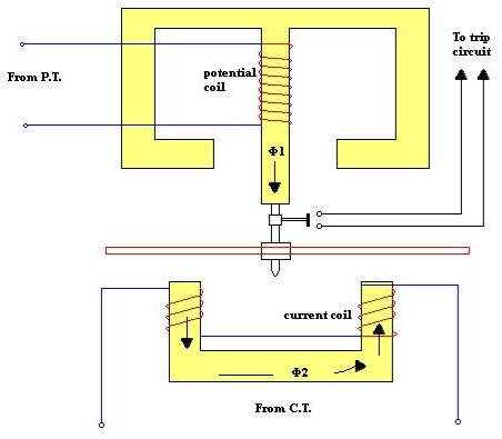
Under normal power flow the trip contacts on the disc spindle are open and the disc bears against a stopWhen reverse power occurs the disc rotates in other direction and moves away from the stop and moves towards the trip relay.
. Line to Neutral Test. Relays are easy to test but often misunderstood. You cant determine phase rotation with a phasor diagram unless you know the one universal rule in the relay testing world.
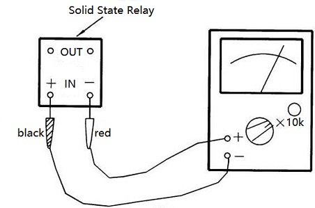
Q a Sketch a simplified circuit of a reverse power relay explain why there is a time delay incorporated before the reverse power relay operates. Connect the red probe to the anode and black probe to the cathode. If the procedure is relying on flexing excitation to produce an effect similar to a reverse power conditon then its a poor procedure relying on the imperfections in the CTs and VTs to fool the relay.
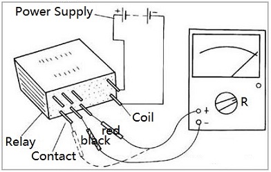
ForwardReverse power circuit Since the two motor starters control only one motor only one set of overload relay heaters need be used. Your current must be in the correct direction. Using a 4 pin relay for our example we must first identify the pins.
Test plugs of either multi-finger or single-finger design for monitoring the current in one CT secondary circuit are used to connect test equipment to the relay under test. No Power Outgoing Test. For example one cycle would be 160second in a 60.
Relays that operate in a minimum time of approximately 01 second. This is the easiest way to do it out of the car and t. Up to 8 cash back The vacuum powers an internal bladder which supplies the force to the hydraulic brake lines.
Lets test your knowledge. You must have a polarizing signal. Keep the selector in low resistance may be 1K ohm mode for forward-bias and keep it in high resistance mode 100K ohm for the reverse bias testing procedure.
List the general rules for the dis assembly of an electric motor. A traditional relay tester or automated testing software will often apply a test scenario like the following. If the vacuum is leaking damaged or the internal components within the power brake booster are damaged it will not work correctly.
The voltage reading should be half of whatever voltage reading was received during the previous test. This video shows you how an automotive relay works and how you can test it using an digital multimeter. Reverse Power element of Numerical Relay calculates the three phase active power using its current and voltage input based on the following formula P V a I a Cos Ø a V b I b Cos Ø b V c IcCos Ø c.
B List the factors that determine the starting torque of the 3-phase induction motor. The return paths for both starter coils connect in series with the normally closed contacts of the overload relay so that if an overload occurs in either direction the starter coils will be de-energized and. An approach to addressing this condition is to set the MTA to 300 or less so that the reverse zone reaches minimally into the forward zone.
Upon the reduced turbine output typically the generator is not able to produce the output power less than no-load losses while the generator is still on-line the generator will operate as a motor and driving the turbine. Your current must be above the pickup setting. The operating time of high-speed relays is usually expressed in cycles based on the power-system frequency.
A relay that functions to prevent overheating of the field excitation winding by reducing or interrupting the excitation of the shunt field. The video below shows you how the waveforms and phasors inter-relate. This current reversal detected by the reverse power relay.
If there is an available neutral terminal place one multimeter probe on that and the other on each of the line terminals. IAICTLIAC 60 field relay power system device function numbers A relay that functions on a given or abnormally low value or failure of machine field current or on an excessive value. Which phase rotation is the following drawing.
Some manufacturers place a diagram and pin ID on the outside of the relay case to show which pins are part of the control circuit and which pins are part of the load circuit. The Numerical Relay is connected with the convention that the forward current is the current flowing from the generator to the busbar. While the box is still off take a reading.
Successful Directional Overcurrent tests have three parts. Explain the electrical principle by which electricity is produced in a generator. The top and bottom contact of each test plug finger is separated by an insulating strip so that the relay circuits can be completely isolated from the switchgear wiring when the test plug is inserted.
The term high speed connotes operation in less than approximately 01 second and usually in 005 second or less. Now slowly increase the output of variable power supply and at the same time observe the voltage shown in the multimeter. 3 Methods for Testing Power Brake Booster Failure.
The relay trips the generator circuit breaker. The reverse bias mode of Zener diode can be easily tested by using the circuit given belowThe resistance R1 can be typically 100 Ohms. Element is to be set below reverse direction load current there is a risk of the element seeing abnormal forward load conditions as reverse fault current as seen in Fig.
The phase rotation is A-B-C. Breaking vacuum to deliberately introduce windage losses onto the turbine in order to test the reverse power relay is possibly the silliest thing. The multimeter must be in voltage mode.
Step 1 - To test for intermitted relay failures which are common remove the relay in question take a small wire strand about two inches long and insert it into the relay connector terminal 87 or 30. ALL PHASORS ROTATE COUNTER-CLOCKWISE. List some of the typical precautions that must be observed in the installment of electric motors.
This test is similar to the test above but tests the outgoing voltage. Explain the adjustment of the limit switches in an actuator circuit. To test the reverse power relay this isnt a test of the breaker just reduce the energy flow-rate into the prime mover until the reverse power relay operated--opening the generator breaker.

Super Easy Generator Reverse Power Trip Youtube

Reverse Power Protection For Generators Youtube
What Is The Difference Between The Reverse Power Relay And The Directional Relay Quora

Reverse Power Protection For Generators Youtube

Measuring Motor Protective Relays Technical Guide Australia Omron Ia
What Is Reverse Power Relay Quora

Reverse Power Relay Basics And Operation

Marine Generator Protection In Reverse Power Under Voltage Situations Bright Hub Engineering

How To Test A Relay With A Multimeter

Reverse Power Protection Marine Engineers Knowledge

Basic Operation Of Oltc And Avr Relay The Avr Relay Ensures That The Download Scientific Diagram

Generator Protection Electrical4u

All About Reverse Power Relay And Preferential Trips On Ship Electrical System Electro Technical Officer Eto
What Is Reverse Power Relay Quora

Forward Reverse Control Circuits Basic Motor Control

All About Reverse Power Relay And Preferential Trips On Ship Electrical System Electro Technical Officer Eto

All About Reverse Power Relay And Preferential Trips On Ship Electrical System Electro Technical Officer Eto


Comments
Post a Comment